Comparative Study of Axial Scanning and Helical Scanning in Craniocerebral Three-Dimensional CT
-
摘要:
目的: 对比研究在颅脑三维CT中使用轴位扫描与螺旋扫描两种模式对图像质量和辐射剂量的影响。方法: 模体研究:对Catphan600模体CTP515 低对比度模块和528高对比模块分别使用临床扫描方案扫描并使用Radia diagnostic软件对图像质量进行评价。临床研究:随机选取使用轴位扫描与螺旋扫描共五台设备的本院2024年8月至2025年1月共298例颅脑CT数据进行回顾性分析。A组147例数据采用螺旋扫描,B组150例数据采用轴位扫描。两组病例均涵盖所有CT设备。测算两组横、冠、矢状面图像客观指标对比度噪声比CNR,并对图像质量进行主观评分。对主客观指标进行统计学分析,P<0.05差异具有统计学意义。使用Radimetrics软件对患者的辐射剂量相关指标进行分析。结果: 整体横断面图像质量轴位扫描优于螺旋扫描,冠矢状面螺旋扫描略优于轴位扫描,容积再现VR图像除设备4外均为螺旋扫描显著优于轴扫。其中横断面CNR设备1具有统计学差异;冠状面主观评分设备2、3、5具有统计学差异;矢状面CNR设备4具有统计学差异,主观评分设备2-5具有统计学差异;VR主观评分设备1、2、3、5均具有统计学差异。所有设备两种扫描模式下扫描长度、DLP、ICRP103差异大于CTDIvol且均具有统计学意义。结论: 在行颅脑CT检查时,扫描模式的选择对图像质量和诊断效果有着重要影响。仅需横断面图像时,轴位扫描能提供满足需求的图像质量,同时患者接受的辐射剂量更低。若需要更优质的VR图像,同时横断、冠状、矢状面图像也能满足临床诊断需求,推荐选用螺旋扫描模式,有条件时可选用宽体探测器单圈轴扫模式。
-
关键词:
- X射线计算机断层成像 /
- 轴位扫描模式 /
- 螺旋扫描模式 /
- 图像质量 /
- 辐射剂量
Abstract:Objective: To conduct a comparative study on the effects of axial and helical scanning modes on image quality and radiation dose in cranial three-dimensional computed tomography. Methods Phantom study: The CTP515 low-contrast module and 528 high-contrast module of a Catphan600 phantom are scanned using clinical scanning protocols, and the image quality is evaluated using the Radia diagnostic software. Clinical study: A total of 298 cranial CT images obtained from five devices in our hospital from August 2024 to January 2025 are randomly selected for retrospective analysis. Among them, 147 cases in group A are scanned in the helical mode, and 150 cases in group B are scanned in the axial mode. All CT devices are used in both groups. The contrast-to-noise ratio, which is an objective index of the transverse, coronal, and sagittal plane images of the two groups, is calculated, and the image quality is scored subjectively. Statistical analysis is performed on the subjective and objective indicators, and P < 0.05 indicates a statistically significant difference. The radiation dose-related indicators of the patients are analyzed using the Radimetrics software. Results In the transverse plane, the image quality obtained via axial scanning is better than obtained via helical scanning. Meanwhile, in the coronal and sagittal planes, the image quality obtained via helical scanning is slightly better than that obtained via axial scanning. Except for device 4, the volume-rendering images based on helical scanning are better than that based on axial scanning. Among them, the CNR of the transverse plane of device 1 indicates a statistically significant difference; the subjective scores of the coronal plane of devices 2, 3, and 5 show statistically significant differences; the CNR of the sagittal plane of device 4 indicates a statistically significant difference; the subjective scores of devices 2–5 in the sagittal plane show statistically significant differences; and the subjective scores of VR of devices 1, 2, 3, and 5 indicate statistically significant differences. The differences in scan length, DLP, and ICRP103 between the two scanning modes of all devices exceed those of CTDIvol, with all being statistically significant. Conclusion When performing cranial CT examinations, the scanning mode selected significantly affects the image quality and diagnostic effectiveness. When only transverse plane images are required, axial scanning can provide an image quality that satisfies the requirements. Meanwhile, patients are exposed to a lower radiation dose if better-quality VR images are required. The transverse, coronal, and sagittal plane images satisfy the clinical diagnostic requirements, and the helical scanning mode is recommended. In certain conditions, a single-rotation axial-scanning mode can be used in conjunction with a wide-body detector.
-
近年来,多排螺旋CT在临床应用中的范围持续拓展,使得CT检查在临床各个科室中的普及程度日益提高,应用愈发广泛。颅脑CT检查是临床中常见的项目,且扫描范围邻近晶状体、甲状腺等辐射敏感器官[1],患者的辐射剂量和潜在风险已受到国内外众多专家学者的密切关注[2]。专家共识[3]一般推荐首选轴扫模式进行颅脑CT扫描,业内也普遍认为轴位扫描的颅脑CT图像质量优于螺旋扫描[4]。但轴位扫描时间长,床位移动次数多,如参数设置不当可能带来伪影;另外部分危急重症和躁动的患者常常不能全程配合[5]。本研究通过对比研究多台设备不同扫描模式的薄层图像经多方位重组(multiplanar reformation,MPR)及容积再现(volume rendering,VR)重组图像质量和辐射剂量进行综合评估,以探讨使用不同类型的设备行颅脑CT检查时所推荐的扫描方式。
1. 资料与方法
1.1 实验设备
美国模体实验室Catphan600性能模体;荷兰Philips IQon Spectral CT扫描仪、德国Siemens SOMATOM Force CT扫描仪、美国GE Revolution evo CT扫描仪、美国GE RevolutionTM CT扫描仪(16 cm宽体探测器)、中国联影 uCT760 扫描仪;Philips星云三维影像数据中心(IntelliSpace Portal,ISP)。
1.2 实验方法
1.2.1 模体实验
使用Philips IQon Spectral CT扫描仪,对Catphan600模体的高、 低对比度分辨力模块进行扫描,固定CT容积剂量指数(CT dose index volume,CTDIvol)为48 mGy,其余扫描参数见表1。使用Radia diagnostic v6.9对图像高低对比分辨力进行分析。
表 1 不同设备扫描参数及重建参数Table 1. Scanning parameters and reconstruction parameters of different devicesPhilips IQon Spectral CT Siemens SOMATOM Force CT GE Revolution evo CT GE Revolution TM CT 联影 uCT760 相同
参数管电压(kV) 120 窗宽窗位(HU) 30/80 矩阵 512×512 迭代/重建算法 iDose4(1) ADMIRE(3) ASiR-V (30%) ASiR-V(50%) KARL 3 D(5) 滤过核 Brain Std (UB) Hr40 Stnd Stnd H_SOFT_B 螺旋
扫描管电流(mAs) 250 360 280 360 283 旋转时间(s) 0.5 1 0.8 0.5 0.8 准直宽度(mm) 16×0.625 96×0.6 32×0.625 64×0.625 32×0.625 螺距 0.935 0.55 0.969 0.156 0.675 扫描范围 第二颈椎至颅顶 层厚/层间距(mm) 1 0.75 0.625 0.625 0.625 轴位
扫描管电流(mAs) 250 300 280 360 273 旋转时间(s) 0.75 Multi 2 1 1 1 准直宽度(mm) 16×0.625 96×0.6 32×0.625 256×0.625 32×0.625 扫描范围 颅底至颅顶 层厚/层间距(mm) 1.25 0.75 0.625 0.625 1.25 注:Philips IQon Spectral CT与联影 uCT760轴位扫描可选择的最薄层厚为1.25 mm。 1.2.2 临床研究资料
回顾性选取2024年8月至2025年1月本院共297例数据,其中男142例,女155例,年龄19~88(51.91±17.70)岁,其中A组为螺旋扫描共147例,B组为轴位扫描共150例。其中设备1共纳入123例,A组60例,B组63例;设备2共纳入54例,A组与B组各27例;设备3、设备4、设备5中,每台设备A组与B组各20例。
排除标准:①检查过程中配合欠佳,存在显著运动伪影;②脑部有金属异物产生明显金属伪影;③因严重颅内占位、脑出血、脑梗死、脑萎缩等影响整体的质量评价或数据测量。
1.2.3 扫描与重建参数(表1)
1.2.4 层面选取与图像重组
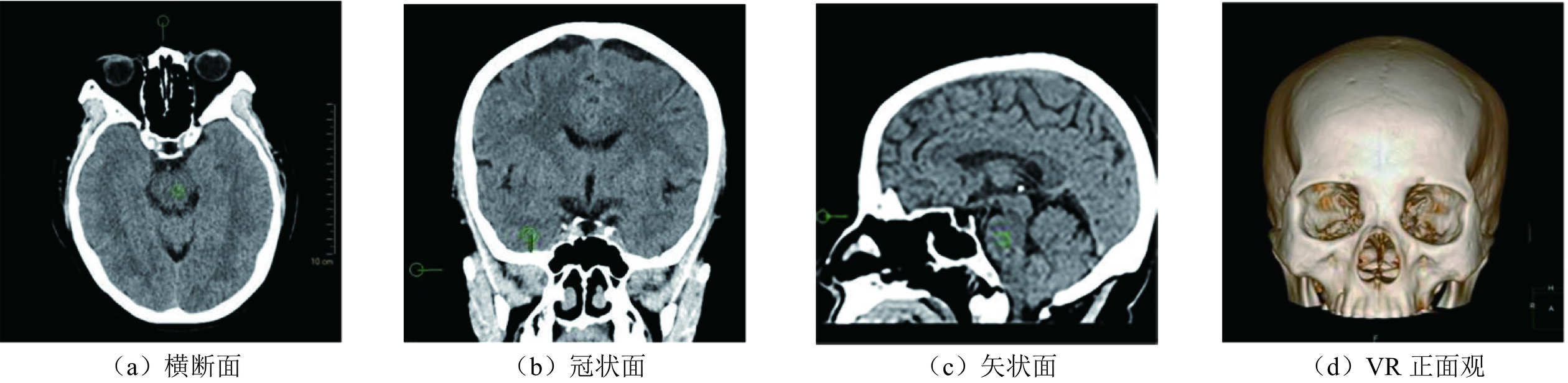
对薄层图像进行MPR及VR重组。MPR:重组层厚为5 mm的横、冠、矢三个方向各选取并保存一个层面:①横断面基线平行于硬腭或颅前窝;②冠状面基线垂直颅中窝;③矢状面取正中矢状面。VR:重组并保存正面观(图1)。
![]() 图 1 示意层面选取与图像重组。患者:女,59岁,采用螺旋扫描并进行MPR和VR重组Figure 1. Layers selected and reformation of patent images (female, 59 years old). Spiral scanning as well as MPR and VR reformations were performed
图 1 示意层面选取与图像重组。患者:女,59岁,采用螺旋扫描并进行MPR和VR重组Figure 1. Layers selected and reformation of patent images (female, 59 years old). Spiral scanning as well as MPR and VR reformations were performed1.2.5 图像质量客观评价
对经MPR所得横、冠、矢三个层面图像进行客观评价,每个层面分别测量感兴趣区(Region Of Interest, ROI) CT 值、背景区CT值以及背景噪声值(SD)[6]。感兴趣区面积为40 mm²,测量时避开线束硬化伪影及运动伪影。①横断面选取脑干层面的中脑或延髓作为 ROI,鼻部上方无遮挡15 mm的空气区作为背景区。②冠状面选取蝶窦层面(视神经管消失前层面)作为ROI,颅中窝上方10 mm的脑组织作为ROI,上颌骨外侧15 mm作为背景区。③矢状面取中脑或延髓作为ROI,鼻骨前方15 mm无遮挡的空气区作为背景区(详见图1)。计算对比噪声比(contrast-to-noise ratio,CNR)(式1):
$$ \mathrm{C}\mathrm{N}\mathrm{R}=\left({\mathrm{C}\mathrm{T}\mathrm{值}}_{\mathrm{R}\mathrm{O}\mathrm{I}}{-\mathrm{C}\mathrm{T}\mathrm{值}}_{\mathrm{背}\mathrm{景}}\right)\div{\mathrm{S}\mathrm{D}}_{\mathrm{背}\mathrm{景}} 。 $$ (1) 1.2.6 图像质量主观评价
两位具有丰富经验的诊断医师和放射技师评估图像质量(双盲法)。横冠矢断层图像评分标准:大脑半球灰白质分界清晰,无阶梯状伪影,脑沟、脑池、脑室显示清晰,3分;大脑半球灰白质分界较清晰,轻微阶梯状伪影,脑沟、脑池、脑室显示较清晰,2分;大脑半球灰白质分界不清晰,严重阶梯状伪影,脑沟、脑池、脑室显示不清晰,1分。VR图像评分标准:无阶梯状伪影,3分;轻微阶梯状伪影,2分;严重阶梯状伪影,1分。当两位医师和技师判断结果不一致时,需协商并判定差异最终达成共识后评分。≥2分即为符合诊断标准[7]。
1.2.7 辐射剂量客观评价
CTDIvol和剂量长度乘积(dose length product,DLP)通过CT剂量报告和获取,有效剂量(International Commission on Radiological Protection Publication 103,ICRP103)和扫描长度通过Radimetrics读取。
1.3 统计学分析
使用SPSS Statistics 26.0软件进行数据分析。非正态分布或方差不齐的连续资料以中位数与四分位数表示。正态分布以平均数和标准差表示。对设备1和设备5矢状面、设备2三个层面、设备3矢状面的CNR进行两独立样本t检验,P<0.05存在统计学意义;对设备1和设备5的横断面和冠状面、设备3的横断面和矢状面、设备4的三个层面的CNR、及VR重组的主观评价、DLP值、ICRP103、扫描长度进行Mann - Whitney U检验,P<0.05存在统计学意义。
2. 结果
2.1 模体实验
轴位扫描低对比度CNR为3.09,内圈靶块(Subslice)可观察到12/12个,外圈靶块(Supraslice)可观察到16/27个,高对比度分辨力为6 LP/cm;螺旋扫描低对比度CNR为2.68,内圈靶块可观察到6/12个,外圈靶块可观察到9/27个,高对比度分辨力为6 LP/cm(图2)。
2.2 图像质量客观评价
设备1的横断面和设备4矢状面存在统计学差异,其余均无统计学差异(表2)。
表 2 不同设备两组MPR图像CNRTable 2. CNR of MPR reformation images for two groups of different devicesA组 B组 t Z P 设备1 横断面 429.40(396.71,492.04) 452.40±92.51 − −2.006 0.045 冠状面 492.19(446.79,541.96) 558.67±99.25 − −0.071 0.944 矢状面 689.61±162.95 698.12±202.69 −1.890 − 0.061 设备2 横断面 487.31±114.40 455.50±73.94 1.197 − 0.237 冠状面 517.447±114.62 562.33±145.79 −1.249 − 0.217 矢状面 648.56±208.63 619.79±170.99 0.548 − 0.586 设备3 横断面 488.67±1.07 540.26(458.20,555.66) − −1.664 0.096 冠状面 565.29±88.56 617.18±98.84 −1.749 − 0.088 矢状面 645.22(580.19,790.15) 637.94±163.56 − −0.933 0.351 设备4 横断面 513.70(474.95,516.36) 527.52±46.97 − −1.393 0.164 冠状面 544.55(516.62,547.18) 495.95(450.15,547.98) − −1.569 0.117 矢状面 557.28(542.33,600.84) 695.28±168.37 − −2.894 0.004 设备5 横断面 544.77(516.73,609.39) 543.98(516.93,546.61) − −0.690 0.490 冠状面 770.30±167.57 742.72(649.45,906.70) − −0.203 0.839 矢状面 858.49±139.79 789.58±187.85 1.316 − 0.196 注:CNR对比噪声比;正态分布资料使用两独立样本t检验;非正态分布资料使用Mann - Whitney U 检验;“−”代表无对应数据。 2.3 图像质量主观评价
设备1 VR图像存在统计学差异,横断面、冠状面、矢状面均无统计学差异,设备2、设备3、设备5除横断面无统计学差异外,其余层面均有统计学差异,设备4仅矢状面有统计学差异(表3)。
表 3 不同设备两组图像质量主观评分Table 3. Analysis of subjective scoring of image quality for two groups of different devicesA组 B组 Z P 设备1 横断面 3(3,3) 3(3,3) −1.869 0.062 冠状面 3(3,3) 3(2,3) −1.350 0.177 矢状面 2(2,3) 2(2,2) −0.113 0.910 VR 3(3,3) 2(2,2) −6.398 0.000 设备2 横断面 3(3,3) 3(3,3) −1.525 0.127 冠状面 3(3,3) 2(2,2) −2.525 0.012 矢状面 3(2.25,3) 2(2,2) −5.468 0.000 VR 3(3,3) 2(2,2) −7.123 0.000 设备3 横断面 3(3,3) 3(3,3) −0.989 0.323 冠状面 2(2,3) 2(2,2) −2.502 0.012 矢状面 2(2,2) 2(2,2) −2.226 0.026 VR 3(3,3) 2(2,2) −5.637 0.000 设备4 横断面 3 3 − − 冠状面 3(3,3) 2(2,3) −1.964 0.050 矢状面 3(2.25,3) 2(2,3) −2.511 0.012 VR 3 3(3,3) −1.000 0.317 设备5 横断面 3(3,3) 3(3,3) −1.433 0.152 冠状面 3(3,3) 2(2,2) −4.377 0.000 矢状面 3(3,3) 2(2,2) −5.204 0.000 VR 3(3,3) 2(2,2) −5.941 0.000 注:非正态分布资料使用Mann - Whitney U 检验;“−”代表无对应数据。 2.4 辐射剂量评价
5台设备的扫描长度、DLP、有效剂量ICRP103均存在统计学差异(表4)。
表 4 不同设备两组辐射剂量及扫描长度比较Table 4. Comparison of radiation dose and scan length between two groups of different devicesA组 B组 降低值 Z P 设备1 CTDIvol(mGy) 48 48 0% − − 扫描长度(mm) 176.00(170.25,196.50) 150.00(150.00,150.00) 14.77% −6.917 0.000 DLP(mGy·cm) 908.0(844.80,955.20) 720.00(720.00,720.00) 20.70% −9.397 0.000 ICRP103(mSv) 2.14(1.96,2.18) 1.88(1.72,1.97) 12.15% −6.490 0.000 设备2 CTDIvol(mGy) 51.18 50.97 0.41% − − 扫描长度(mm) 193.05±12.18 143.99(143.99,148.50) 25.41% −5.339 0.000 DLP(mGy·cm) 976.29±79.61 733.90(733.90,759.25) 24.83% −5.149 0.000 0 ICRP103(mSv) 2.39±0.18 2.03(1.83,2.04) 15.06% −5.378 0.000 设备3 CTDIvol(mGy) 47.61 50.44 −5.94% 扫描长度(mm) 183.65±12.61 160.01(140.53,162.01) 12.87% −4.549 0.000 DLP(mGy·cm) 876.71±57.80 706.22(706.22,807.11) 19.45% −4.639 0.000 ICRP103(mSv) 2.15±0.15 2.01(1.97,2.05) 6.51% −2.880 0.000 设备4 CTDIvol(mGy) 43.97 50.77 −15.47% − − 扫描长度(mm) 201.11±13.58 160.00(159.99,160.00) 20.44% −4.967 0.000 DLP(mGy·cm) 884.29±59.71 812.29(812.29,812.29) 8.14% −3.995 0.000 ICRP103(mSv) 2.19(2.12,2.26) 1.92(1.90,2.18) 12.32% −2.705 0.007 设备5 CTDIvol(mGy) 48.76 48.98 −0.45% 扫描长度(mm) 171.99(166.02,182.21) 140.23(140.00,140.82) 18.47% −5.432 0.000 DLP(mGy·cm) 838.51(809.39,888.66) 686.80(686.64,687.21) 18.09% −5.411 0.000 ICRP103(mSv) 2.17(2.13,2.29) 1.91(1.70,1.92) 11.98% −5.376 0.000 注:非正态分布资料使用Mann - Whitney U 检验,“−”代表无对应数据,降低值为B组比A组降低百分比。 3. 讨论
3.1 图像质量
本研究模体实验结果显示:轴位扫描拥有更好的低对比度分辨力,高对比度分辨力与螺旋扫描无显著差异,与Husby E等[8]的研究结果一致。分析其原因,轴位扫描过程中,X射线管和探测器相对静止,能获取相对稳定的射线衰减数据,每层的数据相对独立且完整,对于低对比度的组织或病变,轴位扫描能更准确地捕捉到细微的密度差异,从而在图像上更好地显示出低对比度区域的细节。
本研究临床研究结果显示,轴位扫描与螺旋扫描的客观评价基本无统计学差异,与刘晓怡[3]、李杨[9]的研究结论一致,且本研究中设备1的轴位扫描横断面显著优于螺旋扫描。分析其原因,模体具有规则、简单且已知的结构,其内部组织的形状、密度分布等都是固定和明确的,轴位扫描在这种稳定的物理环境下,能够更稳定地获取高质量的图像数据,而人体头部结构复杂,包含骨骼、脑组织、血管、脑脊液等多种不同密度和形态的组织,因此临床实验结果无法与模体实验结果完全一致。两种扫描方式主观评分具有显著差异,与于磊[10]的研究中主观评价均无统计学差异的结果有所不同,可能是由于其研究中轴位扫描的CTDIvol高于螺旋扫描。而本研究中轴位扫描的DLP显著低于螺旋扫描,但也保证了所有图像均满足诊断需求。仅设备4的16 cm单圈轴扫模式下VR图像与螺旋扫描时无差异。另外,部分设备轴位扫描时最薄重建层厚高达1.25 mm,而各设备螺旋扫描时重建层厚均可达到最薄层厚0.6 mm左右,这对轴位扫描时MPR和VR图像质量会产生一定的影响。
3.2 辐射剂量
本研究辐射剂量结果显示,轴位扫描相比螺旋扫描DLP显著性降低,与于磊[10]、高志远[11]的研究结果一致。分析其原因,螺旋扫描需要超范围扫描以重建所需图像的最后几层,从而导致扫描长度相对于轴位扫描扫描有所增加。在相同成像范围下,轴位扫描的实际扫描长度小于螺旋扫描,因此在CTDIvol一致的情况下可以降低DLP。本院按照《医用X射线诊断放射防护要求》(GBZ 130—2013)[12]头颅CT诊断参考水平CTDI 50 mGy和各设备特点制定颅脑CT扫描方案;随着《放射诊断放射防护要求》(GBZ 130—2020)[13]的发布,成年受检者头颅CT 的辐射剂量和诊断参考水平CTDIvol为25%位数40 mGy,50%位数50 mGy,75%位数60 mGy;在保证图像质量前提下,适当调整了扫描参数,轴位和螺旋两种扫描模式CTDIvol均低于GBZ 130—2020的60 mGy建议值,符合诊断参考水平。卞冰阳[14]等的研究显示,调节管电流可在保证图像质量的前提下降低敏感器官辐射剂量。Ota J等[15]的研究显示基于器官的管电流调制可以降低 螺旋扫描超范围扫描带来的辐射。
本研究的局限性主要为:临床研究的数据来源于本院各设备的临床扫描方案,虽然已经根据各设备特点和图像质量的差异尽量保持均衡统一的参数设置,扫描范围和CTDIvol尚未做到绝对统一,仍有完善与改进的空间,有待后续进一步研究。
综上所述,在行颅脑CT检查时,扫描模式的选择对图像质量和诊断效果有着重要影响。仅需横断面图像时,轴位扫描能提供满足需求的图像质量,同时患者接受的辐射剂量更低。若需要更优质的VR图像,同时横断、冠状、矢状面图像也能满足临床诊断需求,推荐选用螺旋扫描模式,有条件时可选用宽体探测器单圈轴扫模式。
-
![]()
图 1 示意层面选取与图像重组。患者:女,59岁,采用螺旋扫描并进行MPR和VR重组
Figure 1. Layers selected and reformation of patent images (female, 59 years old). Spiral scanning as well as MPR and VR reformations were performed
表 1 不同设备扫描参数及重建参数
Table 1 Scanning parameters and reconstruction parameters of different devices
Philips IQon Spectral CT Siemens SOMATOM Force CT GE Revolution evo CT GE Revolution TM CT 联影 uCT760 相同
参数管电压(kV) 120 窗宽窗位(HU) 30/80 矩阵 512×512 迭代/重建算法 iDose4(1) ADMIRE(3) ASiR-V (30%) ASiR-V(50%) KARL 3 D(5) 滤过核 Brain Std (UB) Hr40 Stnd Stnd H_SOFT_B 螺旋
扫描管电流(mAs) 250 360 280 360 283 旋转时间(s) 0.5 1 0.8 0.5 0.8 准直宽度(mm) 16×0.625 96×0.6 32×0.625 64×0.625 32×0.625 螺距 0.935 0.55 0.969 0.156 0.675 扫描范围 第二颈椎至颅顶 层厚/层间距(mm) 1 0.75 0.625 0.625 0.625 轴位
扫描管电流(mAs) 250 300 280 360 273 旋转时间(s) 0.75 Multi 2 1 1 1 准直宽度(mm) 16×0.625 96×0.6 32×0.625 256×0.625 32×0.625 扫描范围 颅底至颅顶 层厚/层间距(mm) 1.25 0.75 0.625 0.625 1.25 注:Philips IQon Spectral CT与联影 uCT760轴位扫描可选择的最薄层厚为1.25 mm。  下载: 导出CSV
表 2 不同设备两组MPR图像CNR
Table 2 CNR of MPR reformation images for two groups of different devices
A组 B组 t Z P 设备1 横断面 429.40(396.71,492.04) 452.40±92.51 − −2.006 0.045 冠状面 492.19(446.79,541.96) 558.67±99.25 − −0.071 0.944 矢状面 689.61±162.95 698.12±202.69 −1.890 − 0.061 设备2 横断面 487.31±114.40 455.50±73.94 1.197 − 0.237 冠状面 517.447±114.62 562.33±145.79 −1.249 − 0.217 矢状面 648.56±208.63 619.79±170.99 0.548 − 0.586 设备3 横断面 488.67±1.07 540.26(458.20,555.66) − −1.664 0.096 冠状面 565.29±88.56 617.18±98.84 −1.749 − 0.088 矢状面 645.22(580.19,790.15) 637.94±163.56 − −0.933 0.351 设备4 横断面 513.70(474.95,516.36) 527.52±46.97 − −1.393 0.164 冠状面 544.55(516.62,547.18) 495.95(450.15,547.98) − −1.569 0.117 矢状面 557.28(542.33,600.84) 695.28±168.37 − −2.894 0.004 设备5 横断面 544.77(516.73,609.39) 543.98(516.93,546.61) − −0.690 0.490 冠状面 770.30±167.57 742.72(649.45,906.70) − −0.203 0.839 矢状面 858.49±139.79 789.58±187.85 1.316 − 0.196 注:CNR对比噪声比;正态分布资料使用两独立样本t检验;非正态分布资料使用Mann - Whitney U 检验;“−”代表无对应数据。
下载: 导出CSV
表 3 不同设备两组图像质量主观评分
Table 3 Analysis of subjective scoring of image quality for two groups of different devices
A组 B组 Z P 设备1 横断面 3(3,3) 3(3,3) −1.869 0.062 冠状面 3(3,3) 3(2,3) −1.350 0.177 矢状面 2(2,3) 2(2,2) −0.113 0.910 VR 3(3,3) 2(2,2) −6.398 0.000 设备2 横断面 3(3,3) 3(3,3) −1.525 0.127 冠状面 3(3,3) 2(2,2) −2.525 0.012 矢状面 3(2.25,3) 2(2,2) −5.468 0.000 VR 3(3,3) 2(2,2) −7.123 0.000 设备3 横断面 3(3,3) 3(3,3) −0.989 0.323 冠状面 2(2,3) 2(2,2) −2.502 0.012 矢状面 2(2,2) 2(2,2) −2.226 0.026 VR 3(3,3) 2(2,2) −5.637 0.000 设备4 横断面 3 3 − − 冠状面 3(3,3) 2(2,3) −1.964 0.050 矢状面 3(2.25,3) 2(2,3) −2.511 0.012 VR 3 3(3,3) −1.000 0.317 设备5 横断面 3(3,3) 3(3,3) −1.433 0.152 冠状面 3(3,3) 2(2,2) −4.377 0.000 矢状面 3(3,3) 2(2,2) −5.204 0.000 VR 3(3,3) 2(2,2) −5.941 0.000 注:非正态分布资料使用Mann - Whitney U 检验;“−”代表无对应数据。
下载: 导出CSV
表 4 不同设备两组辐射剂量及扫描长度比较
Table 4 Comparison of radiation dose and scan length between two groups of different devices
A组 B组 降低值 Z P 设备1 CTDIvol(mGy) 48 48 0% − − 扫描长度(mm) 176.00(170.25,196.50) 150.00(150.00,150.00) 14.77% −6.917 0.000 DLP(mGy·cm) 908.0(844.80,955.20) 720.00(720.00,720.00) 20.70% −9.397 0.000 ICRP103(mSv) 2.14(1.96,2.18) 1.88(1.72,1.97) 12.15% −6.490 0.000 设备2 CTDIvol(mGy) 51.18 50.97 0.41% − − 扫描长度(mm) 193.05±12.18 143.99(143.99,148.50) 25.41% −5.339 0.000 DLP(mGy·cm) 976.29±79.61 733.90(733.90,759.25) 24.83% −5.149 0.000 0 ICRP103(mSv) 2.39±0.18 2.03(1.83,2.04) 15.06% −5.378 0.000 设备3 CTDIvol(mGy) 47.61 50.44 −5.94% 扫描长度(mm) 183.65±12.61 160.01(140.53,162.01) 12.87% −4.549 0.000 DLP(mGy·cm) 876.71±57.80 706.22(706.22,807.11) 19.45% −4.639 0.000 ICRP103(mSv) 2.15±0.15 2.01(1.97,2.05) 6.51% −2.880 0.000 设备4 CTDIvol(mGy) 43.97 50.77 −15.47% − − 扫描长度(mm) 201.11±13.58 160.00(159.99,160.00) 20.44% −4.967 0.000 DLP(mGy·cm) 884.29±59.71 812.29(812.29,812.29) 8.14% −3.995 0.000 ICRP103(mSv) 2.19(2.12,2.26) 1.92(1.90,2.18) 12.32% −2.705 0.007 设备5 CTDIvol(mGy) 48.76 48.98 −0.45% 扫描长度(mm) 171.99(166.02,182.21) 140.23(140.00,140.82) 18.47% −5.432 0.000 DLP(mGy·cm) 838.51(809.39,888.66) 686.80(686.64,687.21) 18.09% −5.411 0.000 ICRP103(mSv) 2.17(2.13,2.29) 1.91(1.70,1.92) 11.98% −5.376 0.000 注:非正态分布资料使用Mann - Whitney U 检验,“−”代表无对应数据,降低值为B组比A组降低百分比。
下载: 导出CSV
-
[1] ATLı E, UYANıK SA, ÖĞÜŞLÜ U, et al. Radiation doses from head, neck, chest and abdominal CT examinations: an institutional dose report.[J]. Diagnostic and interventional radiology, 2021, 27(1): 147-151. DOI: 10.5152/dir.2020.19560.
[2] GARBA I, FATIMA AM, ABBA M, et al. Analysis of image quality and radiation dose in routine adult brain helical and wide-volume computed tomography procedures.[J]. Journal of Medical Imaging and Radiation Sciences, 2022, Sep;53(3): 429-436. DOI: 10.1016/j.jmir.2022.05.008.
[3] 中华医学会影像技术分会, 中国医师协会医学技师专业委员会. 创伤性急重症CT检查技术专家共识[J]. 中华放射学杂志, 2023, 57(11): 1165-1173. DOI: 10.3760/cma.j.cn112149-20230310-00176. [4] 刘晓怡, 綦维维, 刘卓, 等. 头颅CT不同扫描方式的图像质量分析[J]. 中国医学影像学杂志, 2017, 25(6): 418-421. DOI: 10.3969/j.issn.1005-5185.2017.06.005. LIU XY, QI WW, LIU Z, et al. Analysis of image quality in cranial CT with different scanning methods. Chinese Journalof Medical Imaging, 2017, 25(6): 418-421. DOI:10.3969/j.issn.1005-5185.2017.06.005.(in Chinese).
[5] 常鑫, 王旭, 冯晨露. CT轴扫描和螺旋扫描模式对颅脑急诊患者影像质量与辐射剂量的影响[J]. CT理论与应用研究, 2015, 24(1): 117-122. doi: 10.15953/j.1004-4140.2015.24.01.14 CHANG XIN, WANG XU, FENG CHEN-LU. The effect of axial and spiral scan mode in emergency head CT on image quality and radiation dosage.[J]. CT Theory and Applications, 2015, 24(1): 117-122. doi: 10.15953/j.1004-4140.2015.24.01.14
[6] 朱蕾, 牛延涛, 张永县, 等. 不同迭代重建算法在眼眶CT中的适用性研究[J]. CT理论与应用研究(中英文), 2024, 33(4): 487-496. DOI: 10.15953/j.ctta.2024.045. ZHU L, NIU Y T, ZHANG Y X, et al. Applicability of different iterative reconstruction algorithms in orbital computed tomography[J]. CT Theory and Applications, 2024, 33(4): 487-496. DOI: 10.15953/j.ctta.2024.045.
[7] 胡嘉诚, 刘云福, 王新艳, 等. 对比剂分次团注联合能量成像获得CTU和CTA联合成像的应用研究[J]. CT理论与应用研究(中英文), 2024, 33(6): 692-700. DOI: 10.15953/j.ctta.2024.148. HU J C, LIU Y F, WANG X Y, et al. Study on the application of CTU and CTA combined imaging by fractional injection combined of a contrast agent with energy imaging[J]. CT Theory and Applications, 2024, 33(6): 692-700. DOI: 10.15953/j.ctta.2024.148.
[8] HUSBY E, SVENDSEN ED, ANDERSEN HK, et al. 100 days with scans of the same Catphan phantom on the same CT scanner.[J]. Journal of applied clinical medical physics, 2017, 18(6): 224-231. DOI: 10.1002/acm2.12186.
[9] 李杨, 庄勋慧, 李伟凯, 等. 宽体探测器CT儿童头部不同扫描模式对辐射剂量及图像质量影响的研究[J]. 中国医疗设备, 2020, 35(4): 65-67,78. doi: 10.3969/j.issn.1674-1633.2020.04.017 LI Y, ZHUANG XH, LI WK, et al. Study on the effects of different scanning modes of wide-area detector CT on radiation dose and image quality in children's head examination.[J]. China Medical Devices, 2020, 35(4): 65-67,78. doi: 10.3969/j.issn.1674-1633.2020.04.017
[10] 于磊, 姜相森, 阴祖栋, 等. 轴位容积扫描与螺旋扫描颅脑CT图像质量与辐射剂量对比观察[J]. 中国辐射卫生, 2019, 28(4): 462-464. doi: 10.13491/j.issn.1004-714x.2019.04.031 YU L, JIANG XS, YIN ZD, et al. Comparative observation of the image quality and radiation dose between axial volume scanning and spiral scanning in cranial CT.[J]. Chinese Journal of Radiological Health, 2019, 28(4): 462-464. doi: 10.13491/j.issn.1004-714x.2019.04.031
[11] 高志远, 隋岩, 刘康, 等. 基于特定条件下头颅模体螺旋扫描与轴位扫描的图像质量和辐射剂量的对比研究[J]. 中国医学装备, 2024, 21(9): 18-22. DOI: 10.3969/j.issn.1672-8270.2024.09.004. [12] 中华人民共和国国家卫生健康委员会. GBZ 130—2013 放射诊断放射防护要求 [S], 2013 [13] 中华人民共和国国家卫生健康委员会. GBZ 130—2020 放射诊断放射防护要求 [S], 2020 [14] 卞冰阳, 王静, 周清晨, 等. 颅脑CT检查患者辐射剂量最优化问题初探[J]. 中华放射医学与防护杂志, 2019, 39(3): 224-229. doi: 10.3760/cma.j.issn.0254-5098.2019.03.012 BIAN B, WANG J, ZHOU Q, et al. An initial exploration of the optimization of radiation dose in cranial CT examination patients.[J]. Chinese Journal of Radiological Medicine and Protection, 2019, 39(3): 224-229.(in Chinese). doi: 10.3760/cma.j.issn.0254-5098.2019.03.012
[15] OTA J, YOKOTA H, KOBAYASHI T, et al. Head CT dose reduction with organ-based tube current modulation.[J]. Medical physics, 2022, 49(3): 1964-1971. DOI: 10.1002/mp.15467.


计量
- 文章访问数: 23
- HTML全文浏览量: 5
- PDF下载量: 6