
Multi-Voltage Threshold Digitization Method
-
摘要:
模数转换器将物理量随时间变化的模拟信号转换为易于储存和处理的数字信号,是自然科学和信息科学的桥梁,也是现代工业与科研中不可或缺的核心基础器件。20世纪20年代以来,随着均匀时域采样的电子学实现和数学理论陆续建立,均匀时域采样成为模数转换领域的基石。此后数十年,正电子发射断层成像、核聚变中子能谱和中微子探测等需要对大量通道高速信号进行采样的应用不断涌现。在这些应用中,基于均匀时域采样的模数转换方案存在功耗大、成本高等缺点,以至于不得不在数字化前进行预处理,从而损失了信号的原始信息。基于值域采样的多电压阈值数字化方法通过若干电压阈值对信号进行采样,再在后端结合先验信息重建信号,使得大量通道高速信号的精确数字化成为可能。目前,多电压阈值数字化方法已被运用在正电子发射断层成像、X射线安检、中子石油测井和质子治疗监测等领域中。本文概述多电压阈值数字化方法的原理,介绍近年来多电压阈值数字化电子学的研究进展,展望多电压阈值数字化方法领域的研究趋势。
-
关键词:
- 正电子发射断层成像 /
- 模数转换器 /
- 时域采样 /
- 值域采样 /
- 多电压阈值数字化方法
Abstract:Analog-to-digital converters (ADCs) transform the analog signals of time-variant physical quantity into digital signals for storing and processing. As the bridge between natural science and information science, ADCs are indispensable in modern industry and scientific research. Since the 1920s, uniform time-domain sampling has become the basic principle in the field of ADCs with the establishment of its electronic implementation and mathematical theory. In the following decades, applications such as positron emission tomography (PET), nuclear fusion neutron spectrum, neutrino detection, etc., which require sampling of many high-speed signals, have emerged one after another. In these applications, ADCs based on uniform time-domain sampling show disadvantages of high power consumption and high cost, so the signal has to be pre-processed before digitalization with losing the original information of the signal. Based on value-domain sampling, the Multi-Voltage Threshold (MVT) method digitizes the signal through several voltage thresholds and then reconstructs the signal with a computer using prior information. The MVT method makes it possible to accurately digitize a large number of high-speed signals. At present, the MVT method has been applied in PET, X-ray security inspection, neutron logging, proton therapy monitoring, etc. This paper outlines the principle of the MVT method, introduces the research progress of MVT electronics in recent years, and further provides an outlook of the MVT research trend.
-
随着对地下空间开发的日趋增加,地下空间的施工与利用安全问题越来越受到广泛关注[1-3]。地下发育的岩溶对于地下空间的开发会造成诸多安全隐患,例如施工过程中可能引起溶洞塌方、渗水和涌水等现象,会对施工人员的安全或者施工进度造成影响[4-6]。此外,发育的岩溶对于我们的生产生活也会造成很多影响,例如岩溶发育可能造成地面沉降甚至开裂,对人民的生命安全和财产安全造成巨大损失[7-8]。
近年来,跨孔地震CT技术已经广泛应用于岩石破碎带、溶洞等探测,为地下空间的开发利用及施工安全提供了重要的技术支撑。例如,苗庆库等[9]利用地震CT技术对京沪、铜九线进行岩溶探测,取得了良好的勘探效果;麦华山等[10]将地震CT法运用在岩溶地区的电厂选址,可视化展现出探测区域的岩溶的空间分布特征,为电厂选址提供了重要依据;谈顺佳等[11]将钻探和地震CT相结合,获得了佛山某地铁区域岩溶发育的分布规律。
由于地震波的折射现象,如果在覆盖层中布置激发点(震源)和接收点,对基岩中岩溶的成像十分不利[11-13],段成龙等[14]避开覆盖层只在基岩中布置激发点和接收点,取得了良好的成像结果。模拟研究结果表明[15-17],在模型中设计的岩溶尺寸较大时,地震CT技术可以获得较好的成像效果,而实际上我们要探测更小尺寸的岩溶。地球物理反演存在多解性是普遍共识,一般情况下,当岩溶规模一定时,孔间距越大未知量就越多,反演的多解性也就越强。
基于此,本文以孔间距、岩溶尺寸及水平间距3个因素为建模基础,采用改进的Moser方法[18-19]进行地震波初至走时计算,运用走时线性插值算法确定射线路径[20-21],利用联合迭代重建法(simultaneous iterative reconstruction technique,SIRT)进行反演[22],研究跨孔地震CT技术对单个岩溶模型成像效果及多个岩溶纵横向分辨力。
1. 跨孔地震CT观测系统
跨孔地震波初至CT成像技术观测系统如图1所示,数值模拟的孔间距设定为10、15和20 m;孔深固定为20 m,左边为激发孔,从孔口到孔底1 m一个激发点;右边为接收孔,从孔口到孔底1 m一个接收点,共计21个接收点,张望角为60°。正反演模型的网格大小均为0.25 m×0.25 m;各个模型围岩的速度均设为3000 m/s;岩溶填充物的速度均设为1500 m/s;激发点和接收点都设在基岩中;建模时不考虑基岩上覆的覆盖层,只考虑岩溶在基岩中的位置及组合情况。
![]() 图 1 跨孔地震CT观测系统示意图Figure 1. Schematic diagram of the source receiver geometry for a cross-hole seismic CT
图 1 跨孔地震CT观测系统示意图Figure 1. Schematic diagram of the source receiver geometry for a cross-hole seismic CT每个模型的正反演情况均用4个图像表达,所有(a)图像为理论模型,(b)图像为模型及叠在其上的地震波射线,(c)图像为根据激发点和接收点及其初至(走时)建立的反演初始模型,(d)图像为反演成像的速度(纵波)剖面,解释的时候是将(d)图像与(a)图像对比,即它们低速的位置及个数对应得越接近反演成像效果就越好。
2. 孔间距对多岩溶水平分辨能力的影响
本节设计的岩溶中心埋深统一为 H=2 m,并且只考虑存在两个岩溶情况,两个岩溶中心间距L有多重变化,岩溶直径D设为 2.5 m和2 m两种情况变化,孔间距设为 20、15和10 m三种情况,观测系统的张望角统一为60°。
当岩溶直径D都是 2.5 m时,正反演结果如图2~图7所示。可以看出:20 m孔间距、10 m岩溶中心间距反演成像结果并不理想,只对一个岩溶进行了有效成像(图2(d)),当岩溶间距增加到14 m时,两个岩溶都能较好地反演成像(图3(d))。当孔间距变为15 m、岩溶中心间距变为11 m时,两个岩溶成像清晰并且位置准确(图4(d)),当岩溶中心间距变减小为10 m和8 m时,两个岩溶成像仍清晰并且位置准确(图5(d)和图6(d));当岩溶中心间距变减小为5 m时,两个岩溶反演成像出现多解,只有一个岩溶位置准确,且出现成像假象(图7(d))。
![]() 图 2 模型1正反演结果(L=10 m, D=2.5 m)Figure 2. The forward and inversion results of the first model
图 2 模型1正反演结果(L=10 m, D=2.5 m)Figure 2. The forward and inversion results of the first model![]() 图 7 模型6正反演结果(L=5 m, D=2.5 m)Figure 7. The forward and inversion results of the sixth model
图 7 模型6正反演结果(L=5 m, D=2.5 m)Figure 7. The forward and inversion results of the sixth model![]() 图 3 模型2正反演结果(L=14 m, D=2.5 m)Figure 3. The forward and inversion results of the second model
图 3 模型2正反演结果(L=14 m, D=2.5 m)Figure 3. The forward and inversion results of the second model![]() 图 4 模型3正反演结果(L=11 m, D=2.5 m)Figure 4. The forward and inversion results of the third model
图 4 模型3正反演结果(L=11 m, D=2.5 m)Figure 4. The forward and inversion results of the third model![]() 图 5 模型4正反演结果(L=10 m, D=2.5 m)Figure 5. The forward and inversion results of the fourth model
图 5 模型4正反演结果(L=10 m, D=2.5 m)Figure 5. The forward and inversion results of the fourth model![]() 图 6 模型5正反演结果(L=8 m, D=2.5 m)Figure 6. The forward and inversion results of the fifth model
图 6 模型5正反演结果(L=8 m, D=2.5 m)Figure 6. The forward and inversion results of the fifth model当孔间距变为10 m、岩溶中心间距仍为5 m时,两个岩溶成像清晰并且位置准确(图8(d)),这是由于孔间距越小,反演变量越少,多解性越弱,跨孔地震波初至CT成像准确度越高。
![]() 图 8 模型7正反演结果(L=5 m, D=2.5 m)Figure 8. The forward and inversion results of the seventh model
图 8 模型7正反演结果(L=5 m, D=2.5 m)Figure 8. The forward and inversion results of the seventh model当孔间距为20 m、岩溶中心间距为12 m、岩溶直径减小为2 m时,只有一个岩溶成像较清晰位置较准确(图9(d));当岩溶中心间距减为10 m时,反演成像比较乱,与正演模型相差甚远(图10(d))。
![]() 图 9 模型8正反演结果(L=12 m, D=2 m)Figure 9. The forward and inversion results of the eighth model
图 9 模型8正反演结果(L=12 m, D=2 m)Figure 9. The forward and inversion results of the eighth model![]() 图 10 模型9正反演结果(L=10 m, D=2 m)Figure 10. The forward and inversion results of the nineth model
图 10 模型9正反演结果(L=10 m, D=2 m)Figure 10. The forward and inversion results of the nineth model当孔间距减为15 m、岩溶中心间距为12 m、岩溶直径仍为2 m时,一个岩溶成像清晰另一个成像较清晰,位置都比较准确(图11(d));当岩溶中心间距减为10 m时,一个岩溶成像清晰另一个成像较模糊,并且出现一个假的低速异常体(图12(d))。
![]() 图 11 模型10正反演结果(L=12 m, D=2 m)Figure 11. The forward and inversion results of the tenth model
图 11 模型10正反演结果(L=12 m, D=2 m)Figure 11. The forward and inversion results of the tenth model![]() 图 12 模型11正反演结果(L=10 m, D=2 m)Figure 12. The forward and inversion results of the eleventh model
图 12 模型11正反演结果(L=10 m, D=2 m)Figure 12. The forward and inversion results of the eleventh model当孔间距减为10 m、岩溶中心间距调整为5 m、岩溶直径仍为2 m时,一个岩溶成像清晰另一个成像较模糊,并且出现一个假的低速异常体(图13(d));当岩溶中心间距增为6 m时,一个岩溶成像清晰另一个成像较清晰,位置都比较准确(图14(d))。
![]() 图 13 模型12正反演结果(L=5 m, D=2 m)Figure 13. The forward and inversion results of the twelfth model
图 13 模型12正反演结果(L=5 m, D=2 m)Figure 13. The forward and inversion results of the twelfth model![]() 图 14 模型13正反演结果(L=6 m, D=2 m)Figure 14. The forward and inversion results of the thirteenth model
图 14 模型13正反演结果(L=6 m, D=2 m)Figure 14. The forward and inversion results of the thirteenth model上述研究表明,当孔深为20 m、孔间距为20 m时,跨孔地震波初至CT成像对于基岩面附近水平排列的两个岩溶是不能很好地反演成像,而当孔深不变孔间距缩小到15 m和10 m时,该技术对尺寸较大且水平间距大些的两个溶洞可以较好地反演成像。
3. 孔间距对多岩溶垂直分辨能力的影响
本节设计3个岩溶垂直均匀排列在模型水平方向的中心,最上部的岩溶中心埋深均为H=2 m,相邻两个岩溶中心间距为L=3.5 m和3 m两种变化,岩溶直径D设为2.5、2和1.5 m三种变化,孔间距设为20、15和10 m三种情况,观测系统的张望角统一为60°。
当岩溶直径D为 2.5 m时,跨孔地震波初至CT成像结果如图15~图17所示。可以看出:20 m、孔间距3.5 m岩溶中心间距反演成像的结果并不理想,存在多个岩溶(低速)假异常,只有顶部一个岩溶成像了,位置较准确(图15(d));当孔间距减为15 m时,3个岩溶反演成像效果好了一些,但仍然存在多个岩溶假异常(图16(d));当孔间距继续减为10 m时,3个岩溶反演成像清晰了,位置准确,几个微弱的岩溶假异常可以排除掉(图17(d))。
![]() 图 15 模型14正反演结果(L=3.5 m, D=2.5 m)Figure 15. The forward and inversion results of the fourteenth model
图 15 模型14正反演结果(L=3.5 m, D=2.5 m)Figure 15. The forward and inversion results of the fourteenth model![]() 图 16 模型15正反演结果(L=3.5 m, D=2.5 m)Figure 16. The forward and inversion results of the fifteenth model
图 16 模型15正反演结果(L=3.5 m, D=2.5 m)Figure 16. The forward and inversion results of the fifteenth model![]() 图 17 模型16正反演结果(L=3 m, D=2.5 m)Figure 17. The forward and inversion results of the sixteenth model
图 17 模型16正反演结果(L=3 m, D=2.5 m)Figure 17. The forward and inversion results of the sixteenth model当岩溶直径D为 2 m、岩溶中心间距为3 m时,跨孔地震波初至CT成像结果如图18~图20所示。可以看出:20 m孔间距反演成像的结果并不理想,存在多个明显岩溶假异常,只有顶部的岩溶成像效果较好,其余两个也隐约成像了,位置较准确(图18(d));当孔间距减为15 m时,3个岩溶反演成像效果有一些提高,但仍然存在多个岩溶假异常(图19(d));当孔间距继续减为10 m时,3个岩溶反演成像清晰了,位置准确,两个孔周微弱的岩溶假异常可以排除掉(图20(d));此时,若当将岩溶的直径D减为1.5 m时,3个岩溶反演成像仍然清晰,位置准确。这说明只要孔间距小到一个合适程度,更小的岩溶也可以探测到(图21(d))。
![]() 图 18 模型17正反演结果(L=3 m, D=2 m)Figure 18. The forward and inversion results of the seventeenth model
图 18 模型17正反演结果(L=3 m, D=2 m)Figure 18. The forward and inversion results of the seventeenth model![]() 图 19 模型18正反演结果(L=3 m, D=2 m)Figure 19. The forward and inversion results of the eighteenth model
图 19 模型18正反演结果(L=3 m, D=2 m)Figure 19. The forward and inversion results of the eighteenth model![]() 图 20 模型19正反演结果(L=3 m, D=2 m)Figure 20. The forward and inversion results of the nineteenth model
图 20 模型19正反演结果(L=3 m, D=2 m)Figure 20. The forward and inversion results of the nineteenth model![]() 图 21 模型20正反演结果(L=3 m, D=1.5 m)Figure 21. The forward and inversion results of the twentieth model
图 21 模型20正反演结果(L=3 m, D=1.5 m)Figure 21. The forward and inversion results of the twentieth model上述研究表明,当孔深为20 m、孔间距为15 m或20 m时,跨孔地震波初至CT成像对于3个直径为2.5 m或2 m岩溶垂直均匀排列(第1个岩溶中心埋深2 m)在模型水平方向中心的岩溶模型,只有顶部1个岩溶成像较准确,其余两个不能很好地反演成像;当孔深不变孔间距缩小到10 m时,岩溶的直径为2.5 m或2 m甚至1.5 m都能很好地反演成像。
4. 孔间距对单个岩溶反演成像的影响
为了将问题简化并与多岩溶模型对比,本节设计单个岩溶模型,分为两种孔间距和两种岩溶中心埋深情况进行正反演模拟研究。
岩溶直径D为2.5 m时,跨孔地震波初至CT成像结果如图22~图26所示。可以看出: 当孔间距20 m,岩溶中心埋深3 m时,反演成像的结果中有与模型对应位置的岩溶(低速)异常体,并且其周围还存在1个明显的假低速异常体及2个弱一点的假低速异常体(图22(d)),当将岩溶向左水平移动到距钻孔5 m时,反演效果较理想,假的低速异常体有所减弱(图23(d));当岩溶中心埋深增至5 m时,反演成像的结果有与模型对应位置的岩溶(低速)异常体,并且其周围还存在4个较明显的假低速异常体(图24(d))。
![]() 图 22 模型21正反演结果(H=3 m,D=2.5 m)Figure 22. The forward and inversion results of the twenty-first model
图 22 模型21正反演结果(H=3 m,D=2.5 m)Figure 22. The forward and inversion results of the twenty-first model![]() 图 23 模型22正反演结果(H=3 m,D=2.5 m)Figure 23. The forward and inversion results of the twenty-second model
图 23 模型22正反演结果(H=3 m,D=2.5 m)Figure 23. The forward and inversion results of the twenty-second model![]() 图 24 模型23正反演结果(H=5 m,D=2.5 m)Figure 24. The forward and inversion results of the twenty-third model
图 24 模型23正反演结果(H=5 m,D=2.5 m)Figure 24. The forward and inversion results of the twenty-third model![]() 图 25 模型24正反演结果(H=3 m,D=2.5 m)Figure 25. The forward and inversion results of the twenty-fourth model
图 25 模型24正反演结果(H=3 m,D=2.5 m)Figure 25. The forward and inversion results of the twenty-fourth model![]() 图 26 模型25正反演结果(H=5 m,D=2.5 m)Figure 26. The forward and inversion results of the twenty-fifth model
图 26 模型25正反演结果(H=5 m,D=2.5 m)Figure 26. The forward and inversion results of the twenty-fifth model当孔间距减小至15 m,岩溶中心埋深仍为3 m时,反演成像的结果有与模型对应位置的岩溶(低速)异常体,其右上方还存在1个较明显的假低速异常体(图25(d));当岩溶中心埋深增至5 m时,反演成像的结果有与模型对应位置的岩溶(低速)异常体,其周围基本不存在较明显的假低速异常体(图26(d))。以上情况表明孔间距越小、异常体越靠近模型中心反演效果越好。
上述研究表明,当孔深为20 m、孔间距为20 m时,跨孔地震波初至CT成像技术对于1个直径为2.5 m、中心埋深为3 m或5 m在模型水平方向中心的岩溶模型反演成像存在明显的低速假异常体,当岩溶向钻孔靠近时,假异常则有所减弱;当孔深不变孔间距缩小到15 m时,以上两种埋深的岩溶都能很好地反演成像。
5. 结论
本文对影响跨孔地震波初至CT成像精度的3个因素(孔间距、岩溶尺寸及水平间距)开展正反演研究。研究结果表明:当孔深为20 m、孔间距为20 m时,跨孔地震波初至CT技术对基岩面附近水平排列的两个岩溶不能很好地反演成像,而当孔深不变、孔间距缩小到15 m和10 m时,该成像技术对尺寸大些、水平间距大些的岩溶能很好地反演成像;当孔深为20 m、孔间距为15 m或20 m时,该成像技术对3个直径为2.5 m或2 m岩溶垂直均匀排列(第1个岩溶中心埋深2 m)在模型水平方向中心的岩溶模型不能很好地反演成像,而当孔深不变、孔间距缩小到10 m时,岩溶的直径为2.5 m或2 m或1.5 m都能很好地反演成像;当孔深为20 m、孔间距为20 m时,该成像技术对单个直径为2.5 m中心埋深为3 m或5 m在模型水平方向中心的岩溶不能很好地反演成像,而当孔深不变孔间距缩小到15 m时,以上两种埋深的岩溶都能很好地反演成像。因此,在实际工作中,为了能准确探测到直径为1.5~2.5 m的岩溶,建议钻孔间距小于15 m。
需要指出的是,地震射线都没有穿过岩溶(低速体)传播(所有(b)图的正演射线),即射线走时里面没有岩溶填充物的速度信息,因此,通过地震波初至CT反演成像的速度剖面无法给出填充物性质的评价,除非岩溶填充物与围岩的速度比较接近时,地震射线才能穿过岩溶采集到其介质速度信息。
-
![]()
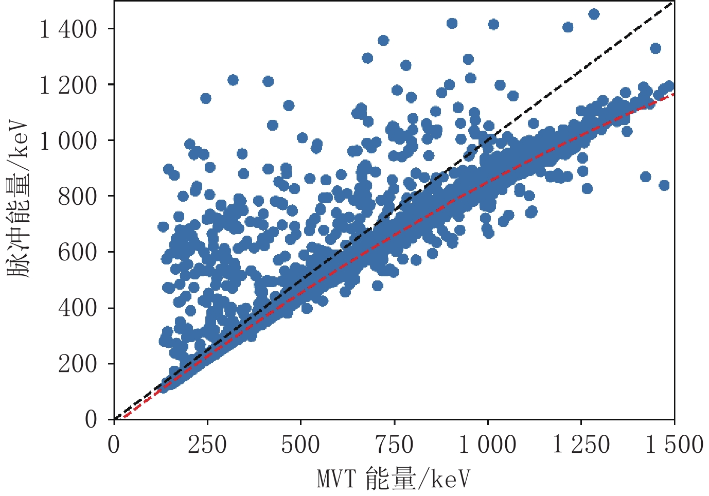
图 2 校正前MVT能量与对应脉冲能量的梯度图。横坐标为MVT能量,纵坐标为对应的脉冲能量,黑色虚线表示
$ E={E}_{\mathrm{M}\mathrm{V}\mathrm{T}} $ 代表的直线,红色虚线代表拟合得到的二次函数Figure 2. Gradient map of MVT energy and corresponding pulse energy before MVT calibration. Black dashed line representing the curve defined by
$ E={E}_{\mathrm{M}\mathrm{V}\mathrm{T}} $ . Red dashed line representing the fitted quadratic function -
[1] WALDEN R H. Analog-to-digital converter survey and analysis[J]. IEEE Journal on Selected Areas in Communications, 1999, 17(4): 539−550. DOI: 10.1109/49.761034.
[2] PEARSON C. High-speed, analog-to-digital converter basics[J]. Texas Instruments Application Report, SLAA510, 2011.
[3] JERRI A J. The Shannon sampling theorem—Its various extensions and applications: A tutorial review[J]. Proceedings of the IEEE, 1977, 65(11): 1565−1596. DOI: 10.1109/PROC.1977.10771.
[4] SHANNON C E. Communication in the presence of noise[J]. Proceedings of the IRE, 1949, 37(1): 10−21.
[5] NYQUIST H. Certain topics in telegraph transmission theory[J]. Transactions of the American Institute of Electrical Engineers, 1928, 47(2): 617−644. DOI: 10.1109/T-AIEE.1928.5055024.
[6] FREDENBURG J, FLYNN M P. ADC trends and impact on SAR ADC architecture and analysis[C]//2015 IEEE Custom Integrated Circuits Conference (CICC). IEEE, 2015: 1-8.
[7] PHELPS M E, HOFFMAN E J, MULLANI N A, et al. Application of annihilation coincidence detection to transaxial reconstruction tomography[J]. Journal of Nuclear Medicine, 1975, 16(3): 210−224.
[8] FUKUDA S, FUKUDA Y, ISHITSUKA M, et al. Constraints on neutrino oscillations using 1258 days of super-Kamiokande solar neutrino data[J]. Physical Review Letters, 2001, 86(25): 5656. DOI: 10.1103/PhysRevLett.86.5656.
[9] BRYSK H. Fusion neutron energies and spectra[J]. Plasma Physics, 1973, 15(7): 611. DOI: 10.1088/0032-1028/15/7/001.
[10] VANDENBERGHE S, MIKHAYLOVA E, D’HOE E, et al. Recent developments in time-of-flight PET[J]. EJNMMI Physics, 2016, 3: 1−30. DOI: 10.1186/s40658-016-0137-4.
[11] SURTI S, KUHN A, WERNER M E, et al. Performance of Philips Gemini TF PET/CT scanner with special consideration for its time-of-flight imaging capabilities[J]. Journal of Nuclear Medicine, 2007, 48(3): 471−480.
[12] JAKOBY B W, BERCIER Y, CONTI M, et al. Physical and clinical performance of the mCT time-of-flight PET/CT scanner[J]. Physics in Medicine & Biology, 2011, 56(8): 2375.
[13] XIE Q, KAO C M, HSIAU Z, et al. A new approach for pulse processing in Positron Emission Tomography[J]. IEEE Transactions on Nuclear Science, 2005, 52(4): 988−995. DOI: 10.1109/TNS.2005.852966.
[14] XI D, ZENG C, MEI X, et al. A digital PET system based on SiPMs and FPGA-only MVT digitizers[C]//2014 IEEE Nuclear Science Symposium and Medical Imaging Conference (NSS/MIC). IEEE, 2014: 1-3.
[15] NIEDŹWIECKI S, BIAŁAS P, CURCEANU C, et al. J-PET: A new technology for the whole-body PET imaging[J]. arXiv Preprint arXiv: 1710.11369, 2017.
[16] MOSKAL P, KISIELEWSKA D, CURCEANU C, et al. Feasibility study of the positronium imaging with the J-PET tomograph[J]. Physics in Medicine & Biology, 2019, 64(5): 055017.
[17] GAO M, CHEN H H, CHEN F H, et al. First results from all-digital PET dual heads for in-beam beam-on proton therapy monitoring[J]. IEEE Transactions on Radiation and Plasma Medical Sciences, 2020, 5(6): 775−782.
[18] ZHAO S, WANG Z, LI M, et al. FPGA-only MVT digitizer for neutron downhole applications[J]. Measurement, 2023, 211: 112649. DOI: 10.1016/j.measurement.2023.112649.
[19] CHEN R, CAI C, LIU W, et al. Multi-voltage threshold digitizer using a time-varied threshold for photon-counting X-ray security inspection imaging[J]. Nuclear Instruments and Methods in Physics Research Section A: Accelerators, Spectrometers, Detectors and Associated Equipment, 2023, 1048: 167886.
[20] JHA A K, Van DAM H T, KUPINSKI M A, et al. Simulating silicon photomultiplier response to scintillation light[J]. IEEE transactions on nuclear science, 2013, 60(1): 336−351. DOI: 10.1109/TNS.2012.2234135.
[21] QIU A, WAN L, LING Y, et al. Energy calibration of MVT digitizers in all-digital gamma cameras[J]. IEEE Transactions on Nuclear Science, 2023.
[22] CARDOSO J F. Blind signal separation: Statistical principles[J]. Proceedings of the IEEE, 1998, 86(10): 2009−2025. DOI: 10.1109/5.720250.
[23] 奚道明. 数字闪烁探测器[D]. 武汉: 华中科技大学, 2015. [24] HENZLER S, HENZLER S. Time-to-digital converter basics[M]. Springer Netherlands, 2010.
[25] DUDEK P, SZCZEPANSKI S, HATFIELD J V. A high-resolution CMOS time-to-digital converter utilizing a Vernier delay line[J]. IEEE Journal of Solid-State Circuits, 2000, 35(2): 240−247. DOI: 10.1109/4.823449.
[26] Van de PLASSCHE R J. CMOS integrated analog-to-digital and digital-to-analog converters[M]. Springer Science & Business Media, 2013.
[27] KIM H, KAO C M, XIE Q, et al. A multi-threshold sampling method for TOF-PET signal processing[J]. Nuclear Instruments and Methods in Physics Research Section A: Accelerators, Spectrometers, Detectors and Associated Equipment, 2009, 602(2): 618-621.
[28] XI D, KAO C M, LIU W, et al. Fpga-only MVT digitizer for TOF PET[J]. IEEE Transactions on Nuclear Science, 2013, 60(5): 3253−3261. DOI: 10.1109/TNS.2013.2277855.
[29] PAŁKA M, STRZEMPEK P, KORCYL G, et al. Multichannel FPGA based MVT system for high precision time (20 ps RMS) and charge measurement[J]. Journal of Instrumentation, 2017, 12(8): P08001. DOI: 10.1088/1748-0221/12/08/P08001.
[30] AMARA A, AMIEL F, EA T. FPGA vs. ASIC for low power applications[J]. Microelectronics Journal, 2006, 37(8): 669−677. DOI: 10.1016/j.mejo.2005.11.003.
[31] NAYAK P. A study of technology roadmap for application-specific integrated circuit[D]. Rice University, 2021.
[32] Application specific integrated circuit (ASIC) technology[M]. Academic Press, 2012.
[33] SEIFERT S, Van der LEI G, Van DAM H T, et al. First characterization of a digital SiPM based time-of-flight PET detector with 1 mm spatial resolution[J]. Physics in Medicine & Biology, 2013, 58(9): 3061.
[34] GRAMUGLIA F, MUNTEAN A, VENIALGO E, et al. CMOS 3D-stacked FSI multi-channel digital SiPM for time-of-flight PET applications[C]//2020 IEEE Nuclear Science Symposium and Medical Imaging Conference (NSS/MIC). IEEE, 2020: 1-3.
[35] D’ASCENZO N, BROCKHERDE W, DREINER S, et al. Design and characterization of a silicon photomultiplier in 0.35-µm CMOS[J]. IEEE Journal of the Electron Devices Society, 2017, 6: 74−80.
[36] NOLET F, DUBOIS F, ROY N, et al. Digital SiPM channel integrated in CMOS 65 nm with 17.5 ps FWHM single photon timing resolution[J]. Nuclear Instruments and Methods in Physics Research Section A: Accelerators, Spectrometers, Detectors and Associated Equipment, 2018, 912: 29-32.
[37] NIKL M. Scintillation detectors for X-rays[J]. Measurement Science and Technology, 2006, 17(4): R37. DOI: 10.1088/0957-0233/17/4/R01.
[38] KATAOKA J, KISHIMOTO A, FUJITA T, et al. Recent progress of MPPC-based scintillation detectors in high precision X-ray and Gamma-ray imaging[J]. Nuclear Instruments and Methods in Physics Research Section A: Accelerators, Spectrometers, Detectors and Associated Equipment, 2015, 784: 248-254.
[39] PEURRUNG A J. Recent developments in neutron detection[J]. Nuclear Instruments and Methods in Physics Research Section A: Accelerators, Spectrometers, Detectors and Associated Equipment, 2000, 443(2/3): 400-415.
[40] SHAO Y. A new timing model for calculating the intrinsic timing resolution of a scintillator detector[J]. Physics in Medicine & Biology, 2007, 52(4): 1103.
[41] DERENZO S E, CHOONG W S, MOSES W W. Fundamental limits of scintillation detector timing precision[J]. Physics in Medicine & Biology, 2014, 59(13): 3261.
[42] DORENBOS P, de HAAS J T M, van EIJK C W E. Non-proportionality in the scintillation response and the energy resolution obtainable with scintillation crystals[J]. IEEE Transactions on Nuclear Science, 1995, 42(6): 2190−2202. DOI: 10.1109/23.489415.
[43] DORENBOS P. Scintillation mechanisms in Ce3+ doped halide scintillators[J]. Physica Status Solidi (a), 2005, 202(2): 195−200. DOI: 10.1002/pssa.200460106.
[44] BIROWOSUTO M D, DORENBOS P. Novel γ- and X-ray scintillator research: On the emission wavelength, light yield and time response of Ce3+ doped halide scintillators[J]. Physica Status Solidi (a), 2009, 206(1): 9−20. DOI: 10.1002/pssa.200723669.
[45] 陈希孺. 概率论与数理统计[M]. 合肥: 中国科学技术大学出版社, 2009. [46] 林元烈. 应用随机过程[M]. 北京: 清华大学出版社有限公司, 2002. [47] RONCALI E, CHERRY S R. Simulation of light transport in scintillators based on 3D characterization of crystal surfaces[J]. Physics in Medicine & Biology, 2013, 58(7): 2185.
[48] BERG E, RONCALI E, CHERRY S R. Optimizing light transport in scintillation crystals for time-of-flight PET: An experimental and optical Monte Carlo simulation study[J]. Biomedical Optics Express, 2015, 6(6): 2220−2230. DOI: 10.1364/BOE.6.002220.
[49] YANG X, DOWNIE E, FARRELL T, et al. Study of light transport inside scintillation crystals for PET detectors[J]. Physics in Medicine & Biology, 2013, 58(7): 2143.
[50] LECOQ P, GUNDACKER S. SiPM applications in positron emission tomography: Toward ultimate PET time-of-flight resolution[J]. The European Physical Journal Plus, 2021, 136(3): 292. DOI: 10.1140/epjp/s13360-021-01183-8.
[51] GRODZICKA-KOBYLKA M, MOSZYŃSKI M, SZCZĘŚNIAK T. Silicon photomultipliers in Gamma spectroscopy with scintillators[J]. Nuclear Instruments and Methods in Physics Research Section A: Accelerators, Spectrometers, Detectors and Associated Equipment, 2019, 926: 129-147.
[52] PIEMONTE C, GOLA A. Overview on the main parameters and technology of modern Silicon Photomultipliers[J]. Nuclear Instruments and Methods in Physics Research Section A: Accelerators, Spectrometers, Detectors and Associated Equipment, 2019, 926: 2-15.
[53] MARANO D, BELLUSO M, BONANNO G, et al. Accurate analytical single-photoelectron response of silicon photomultipliers[J]. IEEE Sensors Journal, 2014, 14(8): 2749−2754. DOI: 10.1109/JSEN.2014.2316363.
[54] GRODZICKA M, SZCZĘŚNIAK T, MOSZYŃSKI M, et al. New method for evaluating effective recovery time and single photoelectron response in silicon photomultipliers[J]. Nuclear Instruments and Methods in Physics Research Section A: Accelerators, Spectrometers, Detectors and Associated Equipment, 2015, 783: 58-64.
[55] GALLEGO L, ROSADO J, BLANCO F, et al. Modeling crosstalk in silicon photomultipliers[J]. Journal of Instrumentation, 2013, 8(5): P05010. DOI: 10.1088/1748-0221/8/05/P05010.
[56] ROSADO J. Modeling the nonlinear response of silicon photomultipliers[J]. IEEE Sensors Journal, 2019, 19(24): 12031−12039. DOI: 10.1109/JSEN.2019.2938018.
[57] Van DAM H T, SEIFERT S, VINKE R, et al. A comprehensive model of the response of silicon photomultipliers[J]. IEEE Transactions on Nuclear Science, 2010, 57(4): 2254−2266. DOI: 10.1109/TNS.2010.2053048.
[58] WEITZEL Q, BERNHARD P, BROGNA A S, et al. Measurement of the response of Silicon Photomultipliers from single photon detection to saturation[J]. Nuclear Instruments and Methods in Physics Research Section A: Accelerators, Spectrometers, Detectors and Associated Equipment, 2019, 936: 558-560.
[59] QIU A, XIE Q. Mathematical considerations in energy spectrum recovery for digital energy spectrometers[J]. IEEE Transactions on Nuclear Science, 2023.
[60] BÉ M M, CHISTÉ V, DULIEU C, et al. Table of radionuclides[M]. 2004.
[61] LLOYD S P. A sampling theorem for stationary (wide sense) stochastic processes[J]. Transactions of the American Mathematical Society, 1959, 92(1): 1−12.
[62] LEE A J. Sampling theorems for nonstationary random processes[J]. Transactions of the American Mathematical Society, 1978, 242: 225−241. DOI: 10.1090/S0002-9947-1978-0482995-6.
[63] YEN J. On nonuniform sampling of bandwidth-limited signals[J]. IRE Transactions on Circuit Theory, 1956, 3(4): 251−257. DOI: 10.1109/TCT.1956.1086325.
[64] MARVASTI F. Nonuniform sampling: Theory and practice[M]. Springer Science & Business Media, 2012.
[65] MISHALI M, ELDAR Y C. Sub-nyquist sampling[J]. IEEE Signal Processing Magazine, 2011, 28(6): 98−124. DOI: 10.1109/MSP.2011.942308.
[66] MISHALI M, ELDAR Y C. From theory to practice: Sub-nyquist sampling of sparse wideband analog signals[J]. IEEE Journal of Selected Topics in Signal Processing, 2010, 4(2): 375−391. DOI: 10.1109/JSTSP.2010.2042414.
[67] FANG J, WANG B, LI H, et al. Recent advances on sub-nyquist sampling-based wideband spectrum sensing[J]. IEEE Wireless Communications, 2021, 28(3): 115−121. DOI: 10.1109/MWC.001.2000353.
[68] YE J C. Compressed sensing MRI: A review from signal processing perspective[J]. BMC Biomedical Engineering, 2019, 1(1): 1−17. DOI: 10.1186/s42490-019-0004-1.
[69] STEIN E M, SHAKARCHI R. Fourier analysis: An introduction[M]. Princeton University Press, 2011.
[70] STEIN E M, SHAKARCHI R. Real analysis: Measure theory, integration, and Hilbert spaces[M]. Princeton University Press, 2009.
[71] ROSS S M. Introduction to probability models[M]. Academic Press, 2014.
-
期刊类型引用(4)
1. 曹波. 城际铁路岩溶综合勘察方法研究. 铁道标准设计. 2024(08): 65-71 .  百度学术
百度学术
2. 蒋益平,陈洪胜,李露瑶,朱小辉,杨正刚,宋小庆,曹振东. 岩溶区地铁盾构隧道下穿水源地综合勘探技术. 隧道建设(中英文). 2023(09): 1541-1548 . 百度学术
3. 王元杰. 基于微震在线监测的实时震源波速反演技术应用. 中国煤炭. 2023(11): 31-38 . 百度学术
4. 许广文,陈军. 岩溶地区地下溶洞勘测探究. 科学技术创新. 2022(16): 109-112 . 百度学术
其他类型引用(0)

 下载:
下载:


计量
- 文章访问数: 399
- HTML全文浏览量: 76
- PDF下载量: 90
- 被引次数: 4
